
How to Choose Wheel Loader Lights for Night Work

Check where the bucket and lift arms interrupt the light before choosing a lamp. On a wheel loader that loads trucks at night, check three positions from the operator’s seat: the bucket entering the pile, the bucket raised over the truck side, and the loader backing away. Each position can call for a different mounting point and beam.
Place the lights around the bucket and lift arms
Front cab roof. Start here for the truck side and loading opening. A higher light may clear the linkage through more of the lift, but the bucket can still cast a shadow near full height. Check the beam at the approach, lift and dump positions. In dust, test whether a roof lamp aimed through the plume washes out the view from the cab. Compare its aim with a lower lamp aimed at the work area.
Front frame or fender. Try an approved mounting point for a flood beam aimed at the cutting edge and the base of the pile. A lower, downward aim can keep more light on the dig face and out of the dust in front of the windscreen. Check clearance through full articulation, bucket travel and tyre movement. Route wiring clear of pinch points and keep the lamp out of the material and tyre spray path where possible.
Rear grille or counterweight. DXZ Engineering uses the reversing leg of the V-pattern cycle to set the rear coverage target. Start with a wide flood aimed across the backing path and rear corners. From the cab, check the mirrors and camera with the lamps on and the machine articulated. A lower mount should leave room for grille airflow, service access and the lamp housing.
DXZ Engineering developed these mounting checks by combining Caterpillar’s loading sequence and NIOSH’s operator sightline diagrams with the beam distributions measured in our laboratory. The loading sequence identifies where the machine and bucket move. The blind-area diagrams show which areas machine structure hides. We use our beam plots to assess light distribution and check the final aim on the loader. Caterpillar loading sequence · NIOSH sightline reference.
Compare lux where the operator needs to see
For a truck side 7 m away, compare illuminance on a vertical surface at that distance with the lamp aimed as it will be on the loader. Use a plot or readings across the side and loading opening. If your site specifies a minimum lux level, check the edges and corners as well as the centre, including any shadow the raised bucket casts. For the reversing path, use a ground-plane plot with the intended mounting height and tilt.

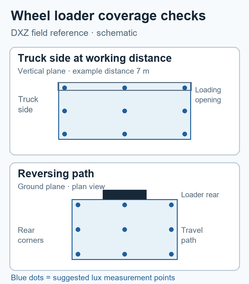
Use a flood or wide flood as a starting point for nearby coverage. Consider a narrower optic where the truck or pile is farther away and the required area is small. A peak candela value helps compare intensity in one direction. A beam plot shows how quickly it falls away toward the edges. Compare measured whole-lamp output under similar test conditions when screening candidates, then verify the coverage on the loader. Read work light beam plots.
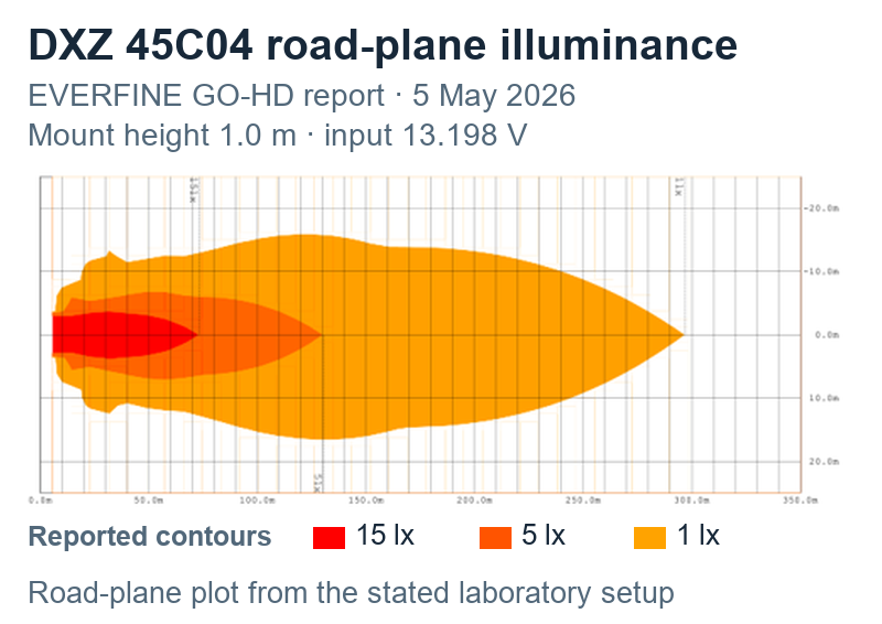
DXZ Laboratory’s 45C04 plot below shows how to read ground-plane contours. The sample was tested at 1.0 m and 13.198 V. Use it as a report example, then compare the vertical truck-side readings or the ground coverage at the mounting height and aim specified for your loader. DXZ beam-map method · DXZ test records.
For a compact flood candidate, compare the DXZ H-37F-16 at the intended front or rear mount. Its product page lists the flood optic and 9–36 V input range. Check the bracket and beam on the machine before choosing it.
Check the 24 V branch under load
The Cat 950 specifications list a 24 V starting and charging system. Check the lighting feed and circuit capacity for your machine’s serial number before connecting lamps. Use the lamp’s input current at the operating voltage, including start-up demand where specified.
For example, four lamps drawing 1.0 A each at 24 V draw 4.0 A on the shared feed. If they share a 6 m feed and a 6 m copper return, both 2.5 mm², the conductor resistance is about 0.084 Ω at 20 °C. At 4.0 A that is about 0.34 V of drop, before connectors and switches. This is a calculation for the shared cable, using 0.0175 Ω·mm²/m for copper. With the lights on, measure the supply and voltage at the farthest lamp. Compare the reading with the lamp’s input range and the machine’s circuit limits. Use the OEM’s circuit protection and wiring requirements when choosing a feed.
Match the test setup to the machine
For washdown and dust exposure, check the ingress report for the lamp as installed. Ask which mating connector, seals and cable exit were on the specimen. A test with a blanking plug describes that configuration. If your harness uses a different interface, ask for evidence for the mated assembly and the relevant dust, immersion or jet exposure. ISO 20653 road-vehicle enclosure test scope.
For a port, fertiliser yard or winter salt operation, agree on the corrosion test method, exposure and acceptance criteria for the actual housing finish, bracket, fasteners and terminals. Ask the supplier to show which parts were tested and how they were inspected. ISO 9227 describes salt spray procedures. The purchase specification sets the hours and the permitted corrosion or coating damage. Compare vibration reports using the proposed bracket and mounting orientation, along with the stated axes and test conditions. ISO 9227 salt spray test scope.
Check the sample through a loading cycle
On a controlled trial with a qualified operator, check the dig face, truck side and reversing path from the cab with the sample aimed and the machine in the relevant positions. Record where the bucket shadows the target, where dust or reflections reduce contrast, and whether the farthest lamp has adequate voltage with the circuit loaded.
For a DXZ enquiry, share the loader make, model and serial range, mounting photos, target distances, measured feed voltage and site exposure. Include the positions where the current lights lose coverage. Request a wheel loader light quote.