
How to Wire LED Work Lights: Relay, Fuse and Switch
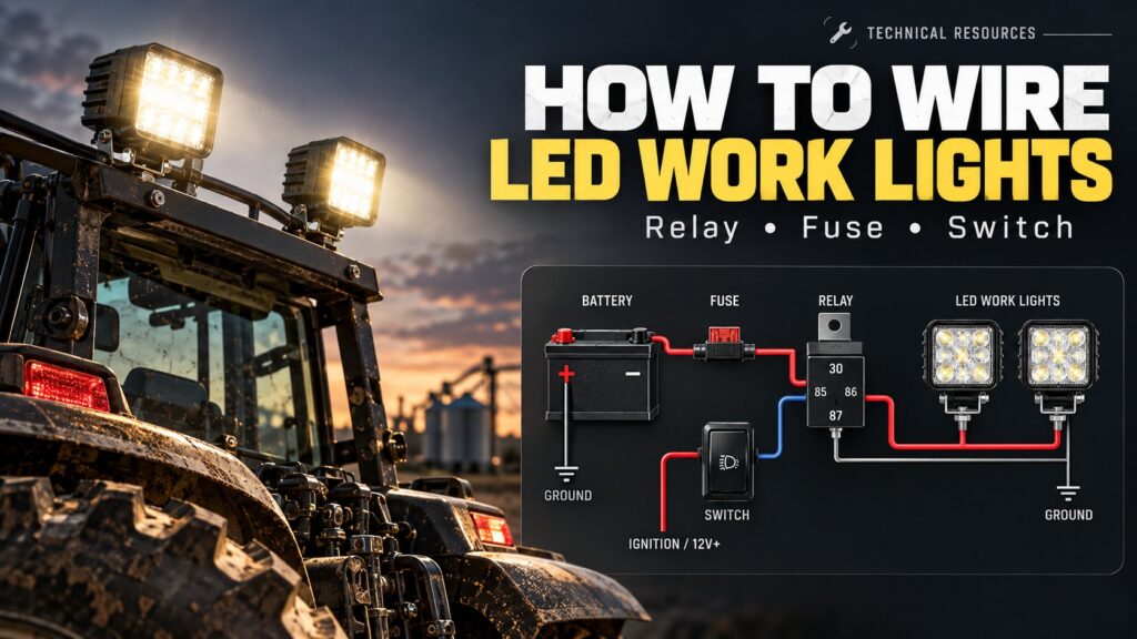
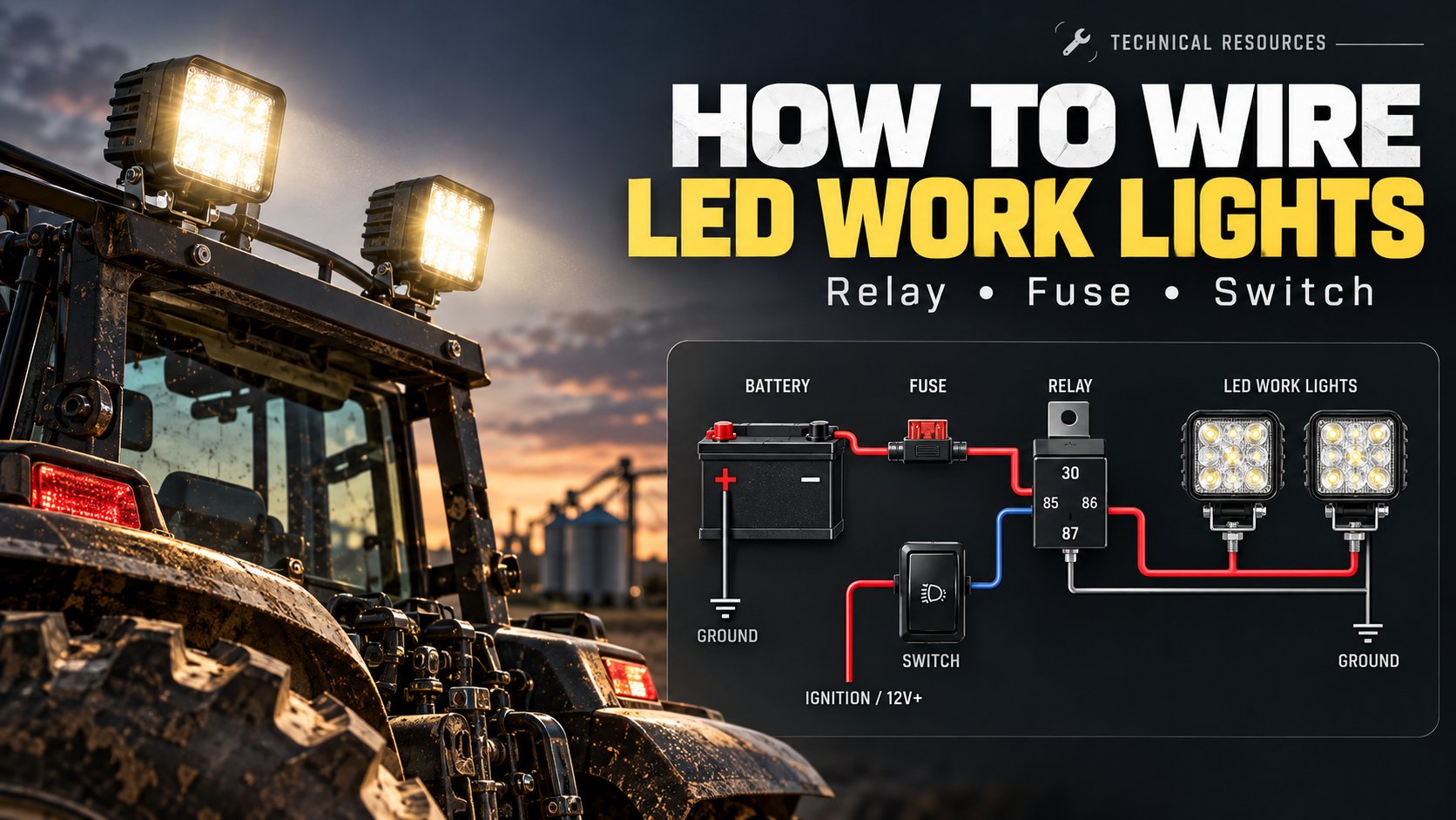
To wire LED work lights with a four-pin relay, feed terminal 30 through a load fuse, connect terminal 87 to the lamps, and use a separately protected switch circuit to energize the coil. Connect each lamp negative and the coil return to vehicle-approved return points. Confirm the actual relay diagram before making connections.
This guide explains an independent switch on a negative-ground 12 V or 24 V DC vehicle. It is a planning example: lamp input limits, relay polarity, circuit protection and vehicle accessory connections must match the equipment you install.
LED work light wiring diagram: follow two circuits
The relay separates the lamp-current path from the switch-operated coil path. With the switch off, the normally-open contact separates 30 from 87. With the coil energized, the contact closes and supplies the lamps.
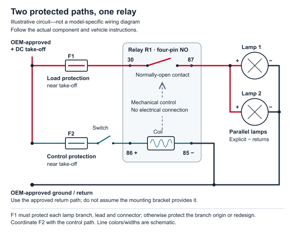
Open the full-size wiring diagram to read the terminal labels and protection notes on a small screen.
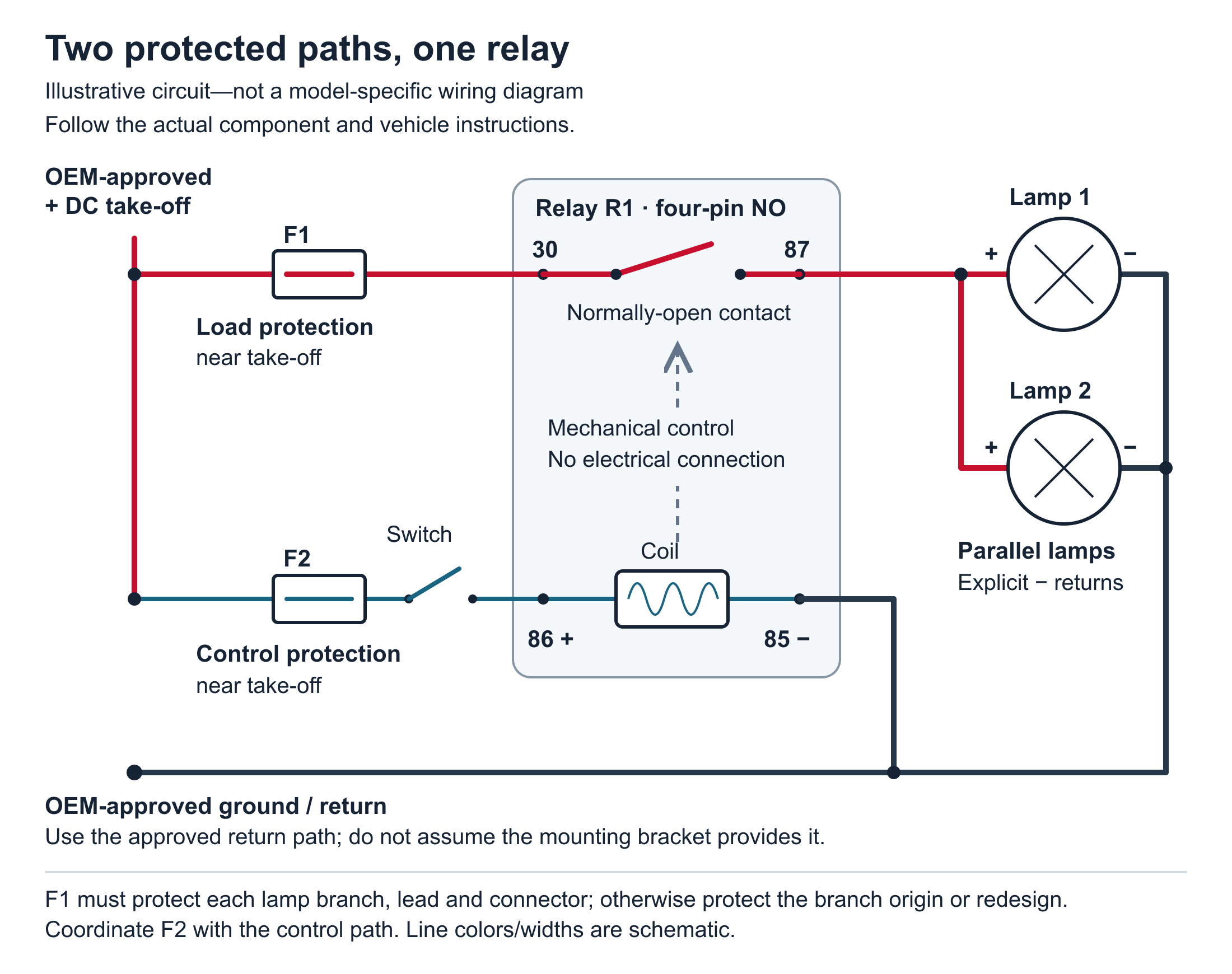
Illustrative circuit. Terminal labels describe functions, not physical pin positions. F1 must protect every downstream lamp branch; otherwise add coordinated branch protection or redesign. Follow the actual component and vehicle instructions.
| Relay terminal | Connection in this example | Purpose |
|---|---|---|
| 30 | Approved supply positive through F1 | Receives the fused lamp supply |
| 87 | Positive leads of the lamps | Supplies the lamps when the contact closes |
| 86 | Approved supply positive through F2 and the switch | Positive coil connection in this example |
| 85 | Vehicle-approved return | Negative coil connection in this example |
Read the numbers on the relay and socket rather than copying a pin layout from a picture. OMRON’s G8V-RH automotive relay diagram illustrates the contact and coil functions; other relay types can use different arrangements.
Load path: approved positive supply → F1 → 30 → relay contact → 87 → each lamp positive. Each lamp negative completes its own approved return path.
Control path: approved positive supply → F2 → switch → 86 → relay coil → 85 → approved return.
Two lamps are connected in parallel here, so each receives the supply voltage. The shared feed and relay contact carry the combined lamp current; each lamp branch carries its own current. Do not assume the mounting bracket provides an electrical return.
What must match before you choose a harness?
Start with the lamp’s electrical specifications and the vehicle’s accessory-installation instructions. A harness is suitable only when its supply, control and load components all fit the installation.
Record these five items:
- Supply and lamp input range. Confirm the vehicle system voltage and the exact lamp’s permitted electrical input.
- Running and start-up current. Use current data for that lamp at the relevant voltage; do not size a circuit from a marketing wattage alone.
- Cable routes. Include the outgoing and return paths, with exposure to heat, abrasion and movement.
- Component ratings. Check the relay coil, DC contacts, socket, switch, connectors and fuse holder individually.
- Approved connection points. Identify the permitted positive take-off, return and any factory accessory interface.
A lamp compatible with both 12 V and 24 V does not make a 12 V relay coil suitable for a 24 V supply. Coil voltage and contact-load capability are separate specifications. Panasonic’s relay precautions explain why coil conditions and actual load characteristics need separate checks.
For vehicles with battery monitoring, the permitted return may differ from a direct battery-negative connection. For example, the 2024 Ford Bronco manual warns against grounding an added device directly at the negative battery post. Use the instructions for your own vehicle.
When comparing DXZ LED work lights, request the exact model’s voltage range and current information before matching a harness.
How do you choose the fuse and wire size?
Choose them together: the cable must carry the installed load without excessive heating or voltage loss, and the fuse must protect the wiring while accommodating permitted operation and start-up. There is no universal fuse or AWG size for every work light installation.
Estimate current, then check the actual lamp data
If electrical input power is known, steady-state current can be estimated as I = P ÷ V. As an arithmetic example, suppose two lamps each consume 48 W at the stated voltage:
| Assumed supply | Combined electrical input | Calculated current |
|---|---|---|
| 12 V | 96 W | 8 A |
| 24 V | 96 W | 4 A |
These are hypothetical inputs, not DXZ product measurements. The calculation assumes the same combined input power at both voltages and does not establish maximum current, start-up current, fuse size or cable size.
Protect the control circuit and every lamp branch
In the diagram, F1 protects the load wiring and F2 protects the switch/coil wiring. Place protection near the approved positive take-off as required by the vehicle and component instructions, minimizing unprotected positive cable. A thin control lead cannot be assumed protected by the larger load fuse.
Check the smaller wires after any split, including factory lamp leads. If upstream protection cannot adequately protect a branch under its installed conditions, provide coordinated protection at that branch’s origin or change the wiring design. Blue Sea Systems’ fuse guidance explains the wire-protection principle; its marine sizing tables are not vehicle-installation defaults.
Fuse selection also depends on ambient temperature, DC voltage, available fault current, start-up pulses and the time-current characteristic. A fuse does not open instantly just because current reaches its printed ampere value. Check the actual fuse data and the manufacturer’s selection method, as outlined in Littelfuse’s selection guide.
Include the return path when assessing voltage drop
Cable sizing needs both a thermal check and a voltage-drop check. Measure the complete route, not just the distance from the source to the lamp. A dedicated return cable adds length; a chassis return needs its actual connections assessed.
Blue Sea Systems’ DC wire-size guide explains round-trip circuit length and temperature-related capacity. Use cable data and voltage limits appropriate to the vehicle and lamp rather than transferring its marine percentages to this installation.
The relay, socket, terminals, connectors and fuse holder also need suitable installed ratings. A current marking on the relay case does not establish the capacity of the assembled harness.
How do you install and check the circuit?
Complete the component and protection checks before assembly. Keep the working circuit de-energized until the wiring is finished and inspected.
- Isolate the relevant supplies. Follow the vehicle’s isolation procedure and verify the work circuit is de-energized. One disconnected cable may not isolate all supplies.
- Route and secure the cable. Keep it clear of hot and moving parts. Protect metal pass-throughs against abrasion, and use terminals, seals and crimps specified for the components.
- Connect the load path. Fit the coordinated protection and connect the approved supply through F1 to 30. Connect 87 to the lamp positives and complete the approved lamp returns.
- Connect the control path. Connect the approved supply through F2 and the switch to 86, then connect 85 to the approved return, subject to the actual relay’s polarity diagram.
- Inspect and test while isolated. Check polarity, terminal functions, coil voltage, branch protection and secure insulation. Use continuity or resistance mode only under the meter’s power-off instructions; a beep does not prove current-carrying performance.
- Restore power and verify operation. Follow the vehicle reconnection procedure. Check switch operation and the lamps under controlled conditions. Isolate the circuit if protection opens, connections heat abnormally or operation is unexplained.
An illuminated switch can have additional terminals for its indicator; use its own diagram. For ignition or factory-lighting control, use the exact OEM-approved interface instructions. This circuit does not authorize tapping vehicle data wires. See Fluke’s continuity-check instructions for power-off measurement conditions.
Why do the lights flicker, stay off or blow a fuse?
Trace the control path first if the relay does not operate. If it operates but the lamps stay off, move to the load path. Avoid replacing parts before identifying where the expected voltage or current path is lost.
| Symptom | First checks | Important limit |
|---|---|---|
| Relay does not operate | F2, switch connections, coil voltage, polarity and return | A lamp’s wide input range does not establish relay-coil compatibility |
| Relay clicks; lamps stay off | F1, supply at 30, switched output at 87, lamp polarity and returns | A click does not prove healthy load contacts |
| Lamps flicker or behave intermittently | Loaded supply and return voltage loss, then individual connections | No-load readings cannot prove the circuit works under current |
| Fuse opens repeatedly | Damaged insulation, polarity, lamp faults and start-up/protection coordination | Isolate the fault; do not bypass or enlarge the fuse to keep operating |
When operation is safe, use DC-voltage mode with the correct meter jacks. Measure supply loss from approved source positive to lamp positive, then return loss from lamp negative to the approved source-side return reference. Prevent probe shorts, check each lamp branch and compare readings with the actual equipment limits. Divide a high-loss path into shorter sections to locate the problem.
An open circuit must be repaired before a meaningful loaded test. Fluke’s automotive voltage-drop guide explains why loaded checks reveal problems that visual inspection can miss.
Frequently asked questions
Can I wire LED work lights without a relay?
Only if the vehicle interface, switch and complete direct-switch circuit are specified for the lamp load, including start-up behavior. A relay lets a suitable low-current switch control a separate lamp-current path, but neither approach removes the need for coordinated circuit protection.
Can two work lights use one relay?
Yes, when the relay and shared wiring are suitable for the combined load and each branch is adequately protected. Connect the lamps in parallel as illustrated, and check the actual specifications of the entire circuit.
Can I use a five-pin relay instead?
Check its circuit first. A changeover relay has an 87a contact connected to 30 when the coil is released; a dual-87 normally-open relay has a different arrangement. HELLA’s relay catalogue shows these variants. Two outputs do not double the stated capacity. Isolate unused connections according to the instructions.
Can I swap terminals 85 and 86?
Do not assume they are interchangeable. A diode-suppressed coil requires the specified polarity. Follow the relay and socket markings rather than testing by reversing the supply. OMRON’s relay troubleshooting note explains the polarity issue.
Does a 24 V system always need thinner wire?
For the same electrical input power, the calculated current is lower at 24 V. That alone does not select the cable: route length, temperature, voltage loss, protection and component ratings still need checking.
Prepare the specifications for your next installation
Before ordering, write down the vehicle voltage, exact lamp model, running/start-up current, cable routes, installation environment and approved supply/return points. These details let you check a proposed harness against the job it must perform.
For a custom lighting project, include those details when contacting DXZ through the OEM and ODM project page. Confirm the lamp’s electrical specifications before finalizing the circuit.
Text version: Read this guide in Markdown